
john deere l120 wiring diagram pdf
The John Deere L120 wiring diagram is essential for diagnosing and repairing electrical issues in your lawn tractor․ It provides a detailed visual representation of the electrical circuits, including the PTO clutch, ignition, and lighting systems․ Whether you’re dealing with PTO engagement failure, blown fuses, or faulty wiring harnesses, the diagram serves as a critical guide․ Available in PDF format, it can be downloaded from official John Deere resources or online forums, ensuring you have the necessary information to maintain and repair your tractor effectively․
1․1 Overview of the John Deere L120 Lawn Tractor
The John Deere L120 is a reliable lawn tractor designed for residential use, offering a balance of power and versatility․ It features a robust Briggs & Stratton or Kohler engine, automatic transmission, and a 42-inch mower deck, making it ideal for maintaining medium-sized yards․ The tractor is part of the L100-L130 series, known for durability and ease of operation․ Its electrical system, including the PTO clutch and wiring harness, is integral to its functionality․ Regular maintenance and repairs often require referencing the wiring diagram to ensure proper diagnostics and troubleshooting․ The L120 is a popular choice for homeowners seeking a dependable and efficient mowing solution․
1;2 Importance of Wiring Diagrams for Repair and Maintenance
Wiring diagrams are crucial for effectively diagnosing and resolving electrical issues in the John Deere L120․ They provide a clear visual representation of the tractor’s electrical system, enabling users to identify components, trace circuits, and locate potential faults․ Whether addressing PTO engagement failures, blown fuses, or faulty wiring harnesses, a wiring diagram is essential for precise troubleshooting․ It also helps prevent further damage by guiding safe and accurate repairs․ Regular maintenance, such as inspecting wiring for wear or corrosion, becomes more efficient with a diagram․ Accessing a John Deere L120 wiring diagram PDF ensures users have the necessary tools to keep their tractor functioning optimally․
Understanding the John Deere L120 Wiring Diagram
The John Deere L120 wiring diagram is a visual guide showing electrical connections and components․ It aids in diagnosing issues, planning repairs, and maintaining the tractor’s system efficiently;
2․1 Key Components of the Wiring Diagram
The John Deere L120 wiring diagram includes essential components like the battery, ignition switch, PTO clutch, fuses, relays, and solenoid․ These elements are interconnected by wires, with labels indicating their purpose․ The diagram highlights the tractor’s electrical system, showing how power flows through circuits․ Key components also include the wiring harness, ground wires, and indicator lights․ Understanding these parts is critical for troubleshooting and repairs, as they form the backbone of the tractor’s electrical functionality․ Each component’s location and role are clearly depicted, making it easier to trace connections and identify potential issues․ This visual representation ensures clarity and precision for maintenance tasks․
2․2 How to Read and Interpret the Diagram
Reading the John Deere L120 wiring diagram requires understanding its symbols and connections․ Start by identifying the main components, such as the battery, ignition switch, and PTO clutch․ Trace the wires to see how circuits are interconnected․ Pay attention to color coding, as it indicates wire purposes․ Use the legend to decode symbols, like fuses or relays․ Follow the flow of power from the battery through switches and relays to the final component․ Verify connections using a multimeter if unsure․ Practice on a known circuit first to build confidence․ This systematic approach ensures accurate troubleshooting and repairs, making the diagram an invaluable tool for maintenance․
2;3 Sources to Access the John Deere L120 Wiring Diagram PDF
The John Deere L120 wiring diagram PDF can be accessed through various reliable sources․ The official John Deere website provides repair manuals and wiring diagrams for purchase or download․ Authorized John Deere dealerships also offer access to these resources․ Additionally, third-party websites specializing in tractor repair manuals may have the PDF available for download․ Ensure the source is trusted to avoid incorrect or incomplete diagrams․ Some online forums and communities dedicated to John Deere equipment may share downloadable versions․ Always verify the authenticity of the diagram to ensure accuracy and safety during repairs․ Using genuine or verified sources is highly recommended․

Common Electrical Issues in John Deere L120
The John Deere L120 often experiences electrical issues like faulty PTO engagement, blown fuses, and wiring harness damage, requiring diagnostic checks and repairs using wiring diagrams․
3․1 PTO Engagement Failure and Electrical Shorts
PTO engagement failure in the John Deere L120 is often linked to electrical issues, such as faulty wiring or solenoid malfunctions․ Electrical shorts can disrupt the PTO clutch circuit, preventing proper engagement․ These problems may stem from damaged connectors, corroded wires, or overload on the system․ A wiring diagram is essential for diagnosing these faults, as it provides a clear map of the PTO circuit․ Common symptoms include intermittent PTO operation or complete failure to engage․ Testing the solenoid, fuses, and wiring connections is crucial․ Regular inspection of the wiring harness and connectors can help prevent such issues, ensuring reliable PTO performance․
3․2 Blown Fuses and Overloaded Circuits
Blown fuses and overloaded circuits are common electrical issues in the John Deere L120․ These problems often occur due to overloading the system with too many accessories or faulty components drawing excessive current․ Symptoms include sudden loss of power to certain functions or dimming of lights․ The wiring diagram helps identify which fuses control specific circuits, allowing for precise troubleshooting․ Inspecting the fuse box and replacing blown fuses are typical solutions․ However, underlying issues like short circuits or malfunctioning relays must be addressed to prevent recurring problems․ Regularly checking the circuit load and ensuring proper connections can minimize the risk of overloaded circuits․ Always refer to the wiring diagram for accurate fuse ratings and circuit layouts․
3․3 Faulty Rio Switch and Wiring Harness Problems
Faulty Rio switches and wiring harness issues are prevalent in the John Deere L120, often causing intermittent electrical failures․ The Rio switch, which controls the reverse implement option, can malfunction due to wear or corrosion, leading to erratic or lost functionality; Wiring harness damage from abrasion or moisture can disrupt connections, affecting multiple systems․ The wiring diagram is crucial for tracing circuits and identifying faulty areas․ Regular inspection of the harness and switch contacts can prevent issues․ Replacing damaged components and ensuring secure connections are typical fixes․ Addressing these problems early prevents further complications and ensures reliable tractor operation․ Always consult the diagram for accurate repairs․
Troubleshooting Electrical Problems
- Identify symptoms like flickering lights or PTO failure․
- Use a multimeter to test circuits and fuses․
- Inspect wiring for damage or corrosion․
- Consult the wiring diagram for circuit layouts․
- Ensure all connections are secure and clean․
Always prioritize safety when diagnosing electrical issues․
4․1 Steps to Identify and Diagnose Electrical Faults
To diagnose electrical faults in your John Deere L120, start by consulting the wiring diagram to understand circuit connections․ Use a multimeter to test voltage and continuity in suspect wires․ Inspect for visible damage, corrosion, or loose connections․ Check fuses and relays for blown or tripped components․ Test switches and sensors for proper function․ Isolate the problem by bypassing or replacing individual components temporarily․ Refer to the wiring diagram to trace circuits and pinpoint faults; Always ensure the tractor is turned off and safety precautions are followed before starting diagnostics․ Regular inspections can help identify issues early, preventing major repairs․
4․2 Tools and Equipment Needed for Troubleshooting
To effectively troubleshoot electrical issues in your John Deere L120, gather essential tools: a multimeter for testing voltage and continuity, a wiring diagram for reference, and a set of screwdrivers for accessing components․ Pliers and wire cutters are useful for repairing or replacing wires․ A fuse tester helps identify blown fuses, while a circuit tester can locate short circuits․ Insulation tape and connectors are handy for securing repairs․ Safety gear, such as gloves and safety glasses, is crucial to protect yourself․ A digital multimeter is particularly important for accurate readings․ Having these tools ensures you can diagnose and repair electrical faults efficiently and safely․
4․3 Common Solutions for PTO Clutch Wiring Issues
For PTO clutch wiring problems in the John Deere L120, start by consulting the wiring diagram to trace the PTO circuit․ Common solutions include replacing blown fuses in the PTO circuit or repairing short circuits in the wiring harness․ Inspect and clean corroded connectors to ensure proper electrical connections․ If the PTO solenoid is malfunctioning, check for power at the solenoid using a multimeter; if no power is present, trace the circuit to identify issues like faulty relays or wiring breaks․ Replace the solenoid if it fails to activate․ Also, ensure the clutch itself is in good condition, as wear can prevent proper engagement․ Always follow safety procedures, such as disconnecting the battery, when working with electrical systems․
Repair and Maintenance Tips
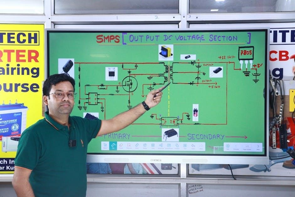
Regularly inspect and clean wiring connections, replace damaged wires, and ensure all components are securely connected․ Use genuine parts and follow the wiring diagram for accuracy․
5․1 Replacing the Wiring Harness
Replacing the wiring harness on a John Deere L120 requires careful planning and adherence to the wiring diagram․ Begin by disconnecting the battery to ensure safety․ Next, locate and remove the old harness, tracing its path through the tractor․ Label each wire connection to avoid confusion during reinstallation․ Use the wiring diagram PDF to verify compatibility and proper routing of the new harness․ Secure all connectors firmly and test each system post-installation․ If issues arise, consult the repair manual or seek guidance from John Deere forums․ Proper installation ensures optimal functionality and prevents future electrical problems․
5․2 Inspecting and Replacing Fuses
Inspecting and replacing fuses in your John Deere L120 is a straightforward process when using the wiring diagram PDF․ Locate the fuse box, typically found under the hood or near the battery, and refer to the diagram to identify the correct fuses․ Turn off the ignition and all electrical components before starting․ Remove the fuse box cover and inspect each fuse for damage or blown states․ Use a multimeter to test for continuity if unsure․ Replace blown fuses with ones of the same amperage rating, as specified in the wiring diagram․ Reassemble the fuse box and test all systems to ensure proper functionality․
5․3 DIY Tips for Maintaining Electrical Systems
Maintaining the electrical system of your John Deere L120 can be done effectively with a few DIY tips․ Regularly inspect connectors and terminals for corrosion or damage, cleaning them with a wire brush if necessary․ Use the wiring diagram PDF to identify circuits and ensure all connections are secure․ Check for frayed or damaged wires and repair or replace them promptly․ Avoid overloading circuits, as this can lead to blown fuses or electrical failures․ When troubleshooting, always disconnect the battery to prevent accidental starts or shocks․ Keep a spare set of fuses and essential tools handy for quick fixes․ Refer to the wiring diagram to trace and resolve issues efficiently․

Understanding the PTO Clutch Wiring Diagram
The PTO clutch wiring diagram guides the electrical connections for engaging and disengaging the power take-off system․ It outlines the circuit for the clutch, solenoid, and safety sensors․
6․1 Detailed Explanation of the PTO Clutch Circuit
The PTO clutch circuit in the John Deere L120 consists of a solenoid, safety switches, wiring harness, fuses, and the clutch assembly․ The solenoid activates the clutch when the PTO switch is engaged․ Safety switches ensure the PTO disengages when the operator leaves the seat or the brake is applied․ The wiring harness connects these components, while fuses protect the circuit from overloads․ Power flows from the battery, through the switches, to the solenoid, and finally to the clutch․ Proper wiring ensures safe and efficient operation․ Regular inspection of connections and components is crucial for maintaining functionality and preventing faults․
6․2 Common Issues with the PTO Clutch Wiring
Common issues with the PTO clutch wiring on the John Deere L120 include worn-out wires, faulty connectors, and short circuits․ Corrosion or damage to the wiring harness can disrupt signal flow․ The PTO solenoid may fail to engage due to electrical faults․ Blown fuses or tripped circuit breakers are frequent problems․ Incorrect wiring connections or loose terminals can prevent the PTO from functioning․ Overloading the circuit or rodent damage to wires also occurs․ Diagnosing these issues often requires consulting the wiring diagram to trace connections and identify faulty components․ Regular inspections and maintenance can help prevent these electrical problems․
6․3 How to Test and Repair the PTO Clutch Wiring
To test the PTO clutch wiring, start by disconnecting the battery to ensure safety․ Use a multimeter to check for voltage at the PTO solenoid and clutch engagement points․ Inspect the wiring harness for cuts, corrosion, or loose connections․ Consult the wiring diagram to verify connections․ If a short or open circuit is detected, repair or replace the damaged section․ For blown fuses, replace them and check for overloaded circuits․ If the solenoid fails, replace it with a compatible part․ After repairs, reconnect the battery and test the PTO clutch function to confirm proper operation․ Always follow safety guidelines when working with electrical systems․
Safety Precautions When Working with Electrical Systems
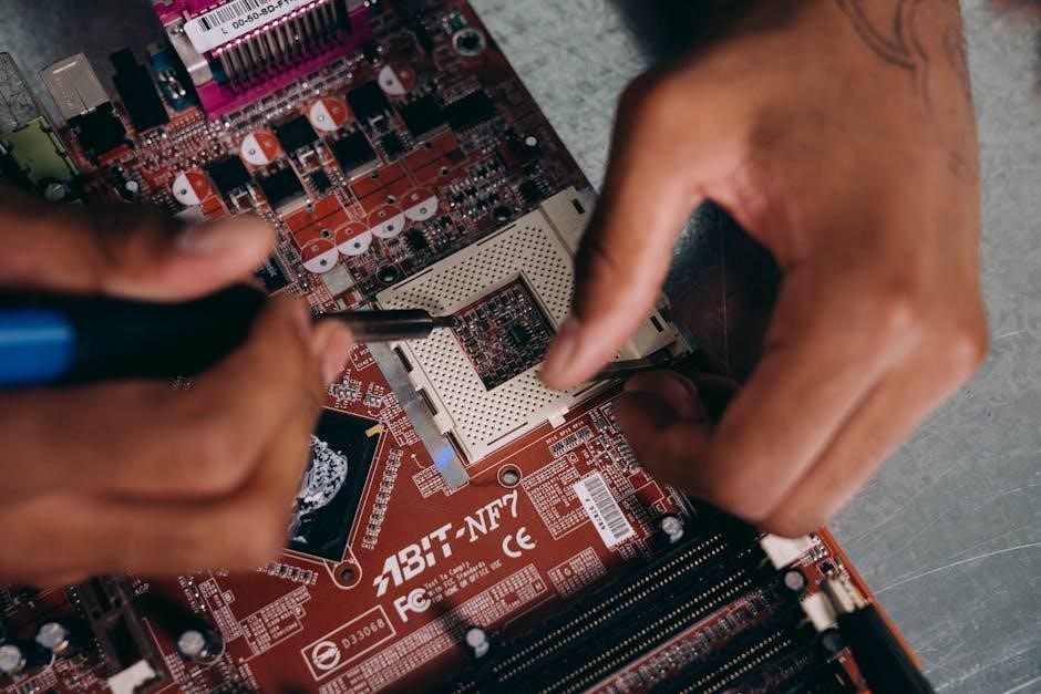
Always disconnect the battery before starting repairs․ Use a multimeter to test live circuits safely․ Wear protective gear, including gloves and goggles․ Avoid working in wet conditions to prevent shocks․ Follow the wiring diagram and manufacturer guidelines to ensure safe repairs․ Never bypass safety features or ignore warning signs․ Properly ground equipment and use insulated tools to minimize risk․ Regularly inspect tools and cables for damage․ Keep a fire extinguisher nearby․ Ensure good ventilation and avoid overheating components․ Stay alert and focused during the repair process․ Never touch electrical components with wet hands or while standing on conductive surfaces․
7․1 Essential Safety Measures for Handling Wiring
When working with the John Deere L120 wiring diagram, always prioritize safety․ Disconnect the battery and ensure the tractor is turned off․ Use a multimeter to verify no live voltage is present․ Wear insulated gloves and safety goggles to protect against electrical shocks or flying debris․ Work in a well-lit, dry environment to reduce slip and shock risks․ Never touch wiring with wet hands or while standing on conductive surfaces․ Secure loose wires to prevent accidental short circuits․ Use properly rated tools and avoid overheating components․ Regularly inspect wiring for damage or wear․ Always ground the tractor before starting repairs․ Follow the wiring diagram carefully to avoid mismatches or overloads․
7․2 Protecting Yourself from Electrical Shocks
Protecting yourself from electrical shocks is crucial when working with the John Deere L120 wiring diagram․ Always disconnect the battery before starting repairs to eliminate power sources․ Use a multimeter to verify no voltage is present in the circuit․ Insulated gloves and non-contact voltage testers are essential tools to prevent direct contact with live wires․ Avoid working in wet conditions or with wet hands, as moisture conducts electricity․ Ensure all tools are properly insulated and rated for the voltage levels involved․ Never bypass safety devices like fuses or circuit breakers․ If unsure, consult the wiring diagram or seek professional assistance to avoid accidents․
7․3 Best Practices for Safe Repairs
Adhering to best practices for safe repairs is essential when working with the John Deere L120 wiring diagram․ Always disconnect the battery and ensure the tractor is in neutral gear with the parking brake engaged․ Use a wiring diagram to guide repairs and verify connections․ Test components before installation to avoid malfunctions․ Wear insulated gloves and safety goggles to protect against electrical hazards or debris․ Work in a well-lit, dry environment to reduce accident risks․ Follow manufacturer guidelines for tool usage and replacement parts․ Double-check all connections and circuits before restoring power․ Testing the system thoroughly after repairs ensures safety and functionality․ Consulting the wiring diagram regularly helps prevent errors and ensures compliance with safety standards․

Resources and References
- Official John Deere repair manuals provide detailed wiring diagrams and repair guides for the L120 model․
- Online forums like GreenPartStore offer DIY tips and troubleshooting advice․
- Essential tools include multimeters, wiring harness kits, and fuse testers․
8․1 Official John Deere Repair Manuals and Guides
Official John Deere repair manuals are the most reliable source for detailed wiring diagrams and repair guides specific to the L120 model․ These manuals are designed to help users understand complex electrical systems, offering accurate schematics and step-by-step instructions․ They include comprehensive coverage of the tractor’s electrical components, such as the PTO clutch, ignition system, and wiring harness․ Available on the John Deere website or through authorized dealers, these resources ensure precise repairs and maintenance․ Additionally, they provide exploded views of components and troubleshooting tips, making them indispensable for both DIY enthusiasts and professional technicians․
8․2 Online Forums and Communities for Support
Online forums and communities are invaluable for troubleshooting and discussions related to the John Deere L120 wiring diagram PDF․ Platforms like GreenTractorTalk and TractorByNet host active discussions where users share experiences, solutions, and resources․ These communities often include threads with PDF links, DIY guides, and expert advice from seasoned tractor owners․ Members can ask specific questions, receiving tailored responses for issues like PTO clutch wiring or electrical system maintenance․ Additionally, these forums provide access to user-generated content, such as modified wiring diagrams and repair tips, offering practical insights beyond official manuals․ Engaging with these communities can save time and effort in resolving complex electrical problems․
8․3 Recommended Tools and Replacement Parts
When working with the John Deere L120 wiring diagram PDF, having the right tools and replacement parts is crucial․ Essential tools include a multimeter for diagnosing electrical issues, a wiring harness repair kit, and a set of fuses compatible with the tractor’s electrical system․ Replacement parts such as PTO clutch wiring, circuit breakers, and connectors are also recommended․ These items can be sourced from official John Deere dealerships or reputable online retailers like Amazon or eBay․ Always opt for high-quality, OEM-compatible components to ensure safety and reliability․ Proper tools and parts are vital for successful repairs and maintaining your tractor’s performance․
Understanding the John Deere L120 wiring diagram PDF is essential for effective troubleshooting and repairs․ This guide provides a comprehensive roadmap for diagnosing and resolving electrical issues, ensuring optimal performance and longevity of your tractor․ By following the outlined steps and using the recommended tools, you can maintain your John Deere L120 efficiently․ Regular maintenance and safe practices are key to preventing future problems․ Refer to official manuals and resources for additional support, ensuring your tractor remains reliable for years to come․
9․1 Summary of Key Takeaways
Understanding the John Deere L120 wiring diagram PDF is crucial for effective troubleshooting and maintenance․ The diagram provides a clear visual representation of the tractor’s electrical system, helping identify components and connections․ Regular inspection of fuses, wiring harnesses, and switches is essential to prevent issues like PTO engagement failures or electrical shorts․ Using the correct tools and following safety protocols ensures safe and efficient repairs․ Referencing official manuals and online resources can further guide DIY enthusiasts․ By mastering the wiring diagram, users can extend the tractor’s lifespan and maintain optimal performance, making it a vital resource for any John Deere L120 owner․
9․2 Importance of Regular Maintenance
Regular maintenance is vital to ensure the longevity and optimal performance of your John Deere L120․ By inspecting the wiring, fuses, and electrical connections, you can prevent issues like shorts or blown fuses․ Referencing the wiring diagram PDF helps identify potential problems early, reducing downtime․ Routine checks also enhance safety, preventing electrical hazards․ Maintaining the tractor’s electrical system ensures smooth operation and extends its lifespan․ Consistent upkeep saves time and money by addressing minor issues before they escalate․ Prioritizing regular maintenance is key to maximizing efficiency and reliability for years of trouble-free operation․
9․3 Final Tips for Successful Repairs

For successful repairs, always reference the John Deere L120 wiring diagram PDF to ensure accuracy․ Use high-quality tools and genuine parts to maintain reliability․ Test repairs thoroughly before full operation to confirm functionality․ Keep the wiring clean and secure to prevent future issues․ If unsure, consult official manuals or seek professional help․ Regularly update your knowledge of the tractor’s electrical system․ Safety first—disconnect the battery before starting work․ Patience and attention to detail are key to avoiding costly mistakes․ Document your repairs for future reference․ By following these tips, you’ll achieve efficient and lasting fixes, ensuring your tractor runs smoothly for years․